Wednesday, 26 August 2015

How to Invoke REST Web services from DataStage Designer

InfoSphere Information Server Designer provides a stage called Hierarchical Data stage  
 (which was called XML Stage in prior releases to V11.3) that has the capability to parse  
 and compose the hierarchical data formats like JSON and XML. Along with that, it  
  provides the capability to invoke the REST Web services.
 It supports the REST Web services that are configured in different ways as below:
 1. That provides the responses in different formats like JSON, XML, HTML, JPEG, Audio  
     etc.
 2. Supports different authentication mechanisms like BASIC, DIGEST, LTPA, OAUTH
 3. Configured with SSL (Server and Client authentication)
 4. Headers and Cookies
 5. Different HTTP methods like GET, POST, PUT, DELETE, PATCH etc.
 Scenario:
 There is so much data on the social media sites, which you want to pull, transform and 
 send for the  analytics. Here I am taking an example of the IBM Facebook page. From 
 which, I want to retrieve the details for how many likes does IBM page have, which 
 all websites talk about IBM, To fulfill the above requirement, You can use our new 
 capability called REST step from the Hierarchical Datastage stage in DataStage Designer.
  Extracting data from Facebook Page
  The Figure 1 illustrates the DataStage job which retrieves the data from Facebook using 
  REST step  and parses the response data from Facebook to fetch the required data for the
 analytics.


 Figure 1: Extract_And_Parse_DataFromFaceBookPage


The figure 2 shows the assembly design of the Hierarchical datastage. The data
is obtained from Facebook by invoking the REST API using REST step. As the 
data provided by Facebook is in format of JSON, JSON parser step is used to parse 
the data. The REST Step “GetFBPageData” and JSON Parser step called 
“ParseFBData” are added to the Assembly Outline.
Figure 2 : Assembly Editor Design

 The Rest Step “GetFBPageData“ is configured as below:
1.In the General tab: The HTTP Method “GET” is selected , URL of the IBM Facebook
   page is mentioned in the “URL” field. The URL is https://graph.facebook.com/IBM as 
   in  figure 3.
2. In the Security tab: As Facebook is configured with SSL, select the checkbox Enable the  
    the SSL and Accept the Self signed certificate as shown in figure 4.
3. In the Request tab: Facebook returns the response in different formats. Here we need in  
    the JSON format. So Specify the Content-Type as application/json under the custom 
    header. As shown in figure 5.
4. In the Response tab : Select the check box “ Pass the received body to” and a radio
    button   “A text node named body in the Output Schema” and specify text/javascript  
    under  the content type as shown in figure 6.
Figure 3: General tab of Rest Step "GetFBPageData"
 Figure 4 : Security tab of Rest Step “GetFBpageData”
 
 Figure 5 : Request tab of Rest Step “GetFBPageData”
 Figure 6 : Response tab of Rest Step “GetFBPageData”
The Output of the REST call which is invoked in the “GetFBPageData” REST step is available in the body element in the output schema tab. The output schema of the REST step is as in figure 7.
Figure 7 : The Output Schema of the Rest Step "GetFBPageData"
 The JSON parser step “ParseFBData” is configured as below:
1.Under the JSON Source tab : Select the String set option, and from the drop down 
   select the bodyelement coming from the REST step “GetFBPageData” as shown in the   
   figure 8.  
2.Under the Document root: Browse and select the schema which conforms with the json
   data retrieved from earlier REST step as shown in figure 9.  
3.Under Validation tab: Minimal Validation is selected by default.  
Figure 8 : JSON Source tab of JSON Parser step “ParseFBData”  
 

 Figure 9 : Document root of JSON Parser step “ParseFBData”


The Output step is configured as below: 

Under the Mappings tab, the target link “DETAILS” is mapped to the top to fetch the parsed details of IBM Facebook page as shown in figure 10.
Figure 10 : Mappings tab of Output step
 
Compile and Execute the job to fetch the required details of the IBM Facebook page shown in figure 11:
Figure 11 : Data from IBM facebook page.
 
 
The output describes the details like ID of the Page, what it is about , when it is founded, 
 how many likes it got, the count talking about this page, username, websites where it is  
 talked etc. This data can be used in the analytics.
Conclusion : The REST capability in the hierarchical Datastage stage can be used to fetch 
 the data like social media data from different applications like Facebook, LinkedIn, 
 Twitter etc which exposes the services using REST
Please also articles published on developer works for the integration scenarios with SOFT 
Layer, Cloudant and Information Governance Catalog Glossary using DataStage.
 http://www.ibm.com/developerworks/data/library/techarticle/dm-1407governrest/index.html 
 Disclaimer: “The postings on this site are my own and don’t necessarily represent IBM’s positions, strategies or opinions.”

Wednesday, 19 August 2015

Some trickey but useful transformation rules

1. How to validate a Email Address

If
AlNum(
Left(inputcolumn,index(inputcolumn, '@', 1) -1 ):Right(inputcolumn,
index(inputcolumn, '@', 1) - 1)
)
Then "Valid" else "Not"

2. How to replace field separator if a string contain any?

Ereplace(EC_File_Nm.$CommandOutput, @FM,'')

it will replace any field separator if any from the command out put of execute command stage.
Lets say the command output is a file name and it contain any filed separator inside it it will be replaced by null.

3. How to get

Monday, 17 August 2015

How to Integrating Web Services with Datastage

Web services expose operations of custom functions accessible to applications through internet or intranet. Web services are interoperable, reusable and follow strict standards and protocols to be followed for accessing them.
SOAP (Simple Object Access Protocol) is a specification for exchanging information between application and Web Service. Web service request and response are encoded in XML format.
This blog is to provide step-by-step instruction on invoking a web service through Datastage.
At the high level, following are the steps to be followed.
  1. Identify and Save Web Service Definition 
  2. Import Web Service Definition 
  3. Configure Web Service Operation 
  4. Configure Web Service Request 
  5. Configure Web Service Response

Identify and Save Web Service Definition

Many web services are publicly available for free. In this example, let us try to access Country web service published through webservicex site.
WSDL definition is listed on the XML frame. 
If you are using Firefox,
Right click on WSDL definition frame
Select “This Frame” option from popup menu
Select “Save frame as” option to locally save the file


If you are using Internet Explorer
          Click on WSDL definition frame
          Select File Menu and Click Save As option to save the file locally

Import Web Service Definition

This step will help to import the WSDL file saved in previous step into Datastage

  • Login to Datastage Designer 
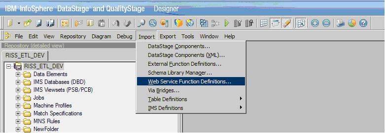
  • Select Web Service Function Definitions in “Import” menu.


  • It opens Web Services browser which lists all the definitions already available on the Datastage project
  •  Click on “Metadata Importer” option


  •  Click on “Open File” option and select the location of WSDL file saved earlier


  • Web service explorer will lists the available web service operations
  • Right click one of the service operation and select Import all operations

 Configure Web Service Operation
Next step is to create a Server Job to access “Country” Web Service through Web Services Client Stage.
  • Login to Datastage Designer and Create a new Server Job 
  • From Palette, Select Web Services Client from Real Time group 
  • Place a sequential file stage as output

  • Open Web Services Client stage properties
  • Click on “Select Web Service Operation”


  • Click on “Select Web Service Operation”
  • Select “GetCountries” option. This web services does not have any input argument to be passed and hence Web Services Client stage is used for data retrieval.


  • Select “GetCountries” option and click on “Select this item” link
If the Datastage server is running behind a proxy for internet access (as most of the site does), configure proxy settings in Proxy tab
  • Enable HTTP/HTTPS option
  • Supply user name and password for accessing internet 
  • Specify proxy host name (without http). If host name and port details are not known, its a general practice to contact Datastage Administrator to obtain such information. 
If Datastage sever and Datastage client machine are directed through same internet proxy, these details can be extracted using the steps below. However, this is not recommended and demonstrated here for test purpose only.


Open Control Panel, Internet Options.
Select LAN Settings from Connections tab


Open the URL specified in LAN settings on a web browser
Host name and port details are generally specified at the “return” statement in configuration script. Supply this information in Web Services Client stage.
NOTE:
  • This would work only when the server is already rightly configured for internet access through proxy 
  • Include the server details in Web Client Stage excluding the file name

Configure Web Service Request

Open Web Services Client stage, Output tab
Open Input Arguments tab
Click on “Load Arguments Information” button. This loads namespace definitions into canvas

Configure Web Service Response

Open Web Services Client stage, Output tab
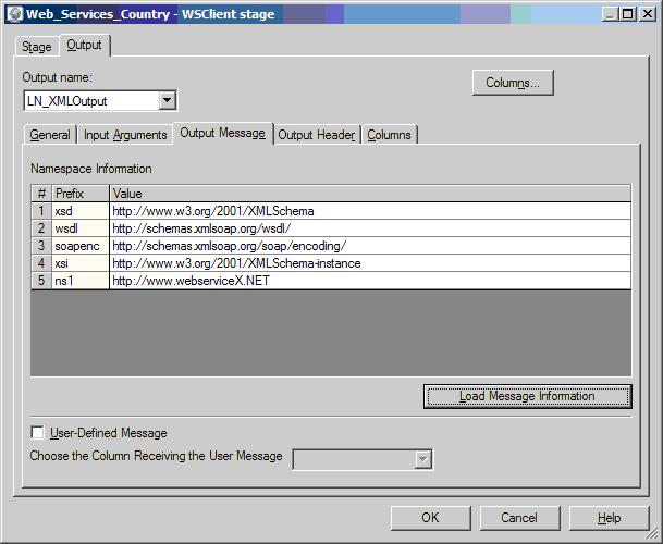
Open Output Message tab
Click on “Load Arguments Information” button. This loads output namespace definitions into canvas

Open Columns tab and check whether output column is populated 


Save, Compile and Run the job
Output file should have contents similar to the following

Tuesday, 23 June 2015

Load XML files using a DataStage Parallel job

Introduction

The intention of this tutorial is to give novice developers a quick start with loading XML data using a DataStage parallel job.

Steps

Step 1:
Create a simple XML file named test.xml
<xml> <customer>Mike</customer> <customer>Anna</customer> </xml>
Step 2:
Create a new DataStage parallel job with 3 stages linked together: A sequential file stage, XML input stage (located under the Real Time category), and a peek stage.
Step 3:
The first trick is to load the entire XML file into a single column of a single row. You do this by creating a column in the sequential file stage of type LongVarChar[Max=9999]. In this example the max size is arbitrary. Set the input file to test.xml. Next, remove all properties in the [Format] tab and add these two:
In the Record level:
Record type=implicit
In the Field defaults:
Delimiter=none
Step 4:
Now that we have the XML in a single column then we can set the XML input stage properties. In the [Transformation settings] tab under the [Stage] tab check the [Repetition element required] tag. In the [Input] tab select the column that you defined in step 3 and check the [XML document] box. In the [Output] tag define a column named [customer] of type varchar[max=255]. Set it as the key. In the description box enter the xml path. In this case /xml/customer/text()
Tip: To reference XML attributes you would use @. For example: /xml/customer/@id would equal 1 when using this xml: <xml><customer id=”1”>Mike</customer></xml>
Step 5:
Compile and run. Peek will produce log records that list the customers from the XML file.

Important Links

https://dstagenotes.wordpress.com/tag/restrict-memory-usage/

http://www.ibm.com/developerworks/data/library/techarticle/dm-0703xiong/

http://www.ibm.com/developerworks/data/library/techarticle/dm-1112isanalyzerrules/

http://www.ibm.com/developerworks/data/tutorials/dm-1108isqualitystagestddata/

http://www.ibm.com/developerworks/library/ws-complexws/

http://www.redbooks.ibm.com/redbooks/pdfs/sg247987.pdf

http://talentain.com/resources/datastage-slowly-changing-dimensions

https://dstagenotes.wordpress.com/2014/04/27/slowing-changing-dimension-using-scd-stage-in-datastage/

https://datastage4u.wordpress.com/2011/04/30/join-stage/

http://datastagetool.blogspot.in/

https://datastage4u.wordpress.com/2012/04/25/infosphere-information-server-datastage-change-data-capture/

http://mydatastage-notes.blogspot.in/p/datastage-study-material.html

http://www.dstagebox.com/

http://www.folkstalk.com/2011/07/datastage-scenario-based-questions-part_3990.html

http://www-01.ibm.com/support/docview.wss?uid=swg21452589

http://www-01.ibm.com/support/docview.wss?uid=swg21663830

https://dstagenotes.wordpress.com/

http://shortcut-tricks.blogspot.in/2016/04/what-is-partition-in-oracle-11g-with.html

http://www.ibm.com/support/knowledgecenter/SSZJPZ_11.3.0/com.ibm.swg.im.iis.ds.deploy.help.doc/topics/depcreate.html

https://books.google.co.in/books?id=ifLHAgAAQBAJ&pg=PA79&lpg=PA79&dq=deployment+tool+for+ibm+datastage+code+integration&source=bl&ots=0BUFpf_7Qk&sig=yhlSS5C8JUQ_aoi9VdUFN0u8R1s&hl=en&sa=X&ved=0ahUKEwjVqLbxk6HRAhVEvxQKHfKoAF8Q6AEINzAF#v=onepage&q=deployment%20tool%20for%20ibm%20datastage%20code%20integration&f=false

Monday, 22 June 2015

SWITCH Stage in Datastage

Switch Stage in Datastage:
  • Switch stage is a Processing Stage. It has one Input Link and number of output links depending upon the ‘cases’ mentioned. Maximum it can have 128 numbers of output links and one reject link.
  • Function of Switch stage in Datastage is analogues to the Switch Statement in ‘C’ Language. For specific output required, there is specific ‘Case’ situation. As it has one Reject Link, those records which are not matched with any of the case will move to the reject link.

Let’s try to configure this Switch stage.
Consider following table
ID
First Name
Last Name
Location
Network ID
EmailID
1
Jach
Simmons
LA
JS524
Letsc@gmail.com
2
Shumas
Jane
Las
Sj145
Jaene@ymail.com
3
Jonty
Waughn
Syd
JW927
JontyW@sdbh.com
3
Suhana
Safar
Mexico
SS99
Sas@gmail.com
8
Abc
Cde
Mex
ab254
lmn@gmail.com
4
Shumas
Jane
Las
Sj145
Jaene@ymail.com
Step 1: Design your job Structure like below.
1
Configure input Sequential file sf_emp_det with above table.
Step 2:Now, to configure Switch stage, double click on it. Following window will pop up.
2
There are three categories under ‘Properties’ tab.
  1. Input
  2. User-defined Mapping
  3. Options
Let’s study one by one.
Step 3:
  1. Input: ‘Selector’ is field through which we have to select a column according to which ‘cases’ are going to be decide. Here, ‘Selector’ = ID.
In ‘Selector Mode’ as we are going to decide cases for this stage, it should be selected as ‘User-
defined Mappings’.
  1. User-defined Mappings:  Here we are going to actually decide the case statements. As shown above, for case 1, 2, 3 and 8 are all ‘ID’ values and 0, 1, 2 are all link labels which we are getting from ‘Link Ordering’ tab.
Refer following window where in right pane ‘link label’ for corresponding ‘Link name’ is given.These ‘link label’s’ are used to define cases as follows.

ID
Link Label
Link Name
Case
1
0
lnk_ID_1
Case
2
1
lnk_ID_2
Case
3
2
lnk_id_3
Case
8
5(Discard Value)

For record ID=8 will get discarded. For discarded value, ‘Link Label’ could be anything. Here is 5. Those records which are not matched with case’s get rejected and stored it in ‘Reject link’, here ‘rjct_id_4’.
3
3. Options:
Discard value: This is like giving the ‘link label’ to discarded link. Consider our case, ‘case=8=5’. For record ID=8 will get   routed to the link 5 which is mentioned here as ‘Discarded value’.
If not found: It decides action to be taken on the records which are failed to match with case statement.
  1. Drop: It will drop the entire row
  2. Fail: It will cause the job to fail.
  3. Output: It will route that particular row to the reject link.
Note: Reject link is not allowed with the ‘Drop’ and ’Fail’ condition. It will throw error during compilation.
Step 4: Let’s see what will happen to the output!!
Compile and run the job. We will see output link by link.
  1. Link lnk_ID_1 for which ‘Case=1=0’.
4
  1. Link lnk_ID_2 for which ‘Case=2=1’.
5
  1. Link lnk_id_3 for which ‘Case=3=2’.
6
  1. For Reject link lnk_rjct_id_4 :As we didn’t mention any case statement for ID=4, it will get route to the reject link.
7
  1. For ‘Case=8=5’: Record for ID=8 get discarded.

PIVOT ENTERPRISE Stage in Datastage

Pivot enterprise stage is a processing stage which pivots data vertically and horizontally depending upon the requirements. There are two types
  1. Horizontal
  2. Vertical
Horizontal Pivot operation sets input column to the multiple rows which is exactly opposite to the Vertical Pivot Operation. It sets input rows to the multiple columns.
Let’s try to understand it one by one with following example.
  1. Horizontal Pivot Operation.
Consider following Table.
Product Type
Color_1
Color_2
Color_3
Pen
Yellow
Blue
Green
Dress
Pink
Yellow
Purple
Step 1: Design Your Job Structure Like below.
Job structure for Pivot Enterprise stage
Configure above table with input sequential stage ‘se_product_clr_det’.
Step 2: Let’s configure ‘Pivot enterprise stage’. Double click on it. Following window will pop up.

Select ‘Horizontal’ for Pivot Type from drop-down menu under ‘Properties’ tab for horizontal Pivot operation.
Step 3: Click on‘Pivot Properties’ tab. Under which we need to check box against ‘Pivot Index’. After which column of name ‘Pivot_Index’ will appear under ‘Name’ column also declare a new column of name ’Color’ as shown below.

Step 4:  Now we have to mention columns to be pivoted under ‘Derivation’ against column ‘Color’. Double click on it. Following Window will pop up.

Select columns to be pivoted from ‘Available column’ pane as shown. Click ‘OK’.
Step 5: Under ‘Output’ tab, only map pivoted column as shown.

Configure output stage. Give the file path. See below image for reference.
6
Step 6: Compile and Run the job. Let’s see what is happen to the output.

This is how we can set multiple input columns to the single column (As here for colors).
Vertical Pivot Operation:
Here, we are going to use ‘Pivot Enterprise’ stage to vertically pivot data. We are going to set multiple input rows to a single row. The main advantage of this stage is we can use aggregation functions like avg, sum, min, max, first, last etc. for pivoted column. Let’s see how it works.
Consider an output data of Horizontal Operation as input data for the Pivot Enterprise stage. Here, we will be adding one extra column for aggregation function as shown in below table.
Product
Color
Prize
Pen
Yellow
38
Pen
Blue
43
Pen
Green
25
Dress
Pink
1000
Dress
Yellow
695
Dress
purple
738
Let’s study for vertical pivot operation step by step.
Step 1: Design your job structure like below. Configure above table data with input sequential file ‘se_product_det’.

Step 2: Open Pivot Enterprise stage and select Pivot type as vertical under properties tab.

Step 3: Under Pivot Properties tab minimum one pivot column and one group by column. Here, we declared Product as group by column. Color and prize  as Pivot columns.Lets see how to use ‘Aggregation functions’ in next step.

Step 4: On clicking Aggregation functions required for this column for particular column following window will pop up. In which we can select functions whichever required for that particular column. Here we are using ‘min’, ’max’ and ‘average’ functions with proper precision and scale for Prize column as shown.

Step 5: Now we just have to do mapping under output tab as shown below.

Step 6: compile and Run the job. Lets see what will be the output is.
Output :